Embedded journey's start
Published at Apr 8, 2024
Spark
I have used microcontrollers to build my corne keyboard, I followed the build guide for the hardware part and compiled/flashed the code successfully. But it was a pre-baked project, the sensation of fixing 🧰 and learning 📖 from problems was lost and replaced with a TODO list, it only help me to gain some confidence in electronics. I am curious on learning more about embedded systems and this is the start.
Microcontroller
I take as subject of study the Atmel Mega 2560 (chip in the Arduino Mega) and I will explore its cpu and memory capabilities in its datasheet.
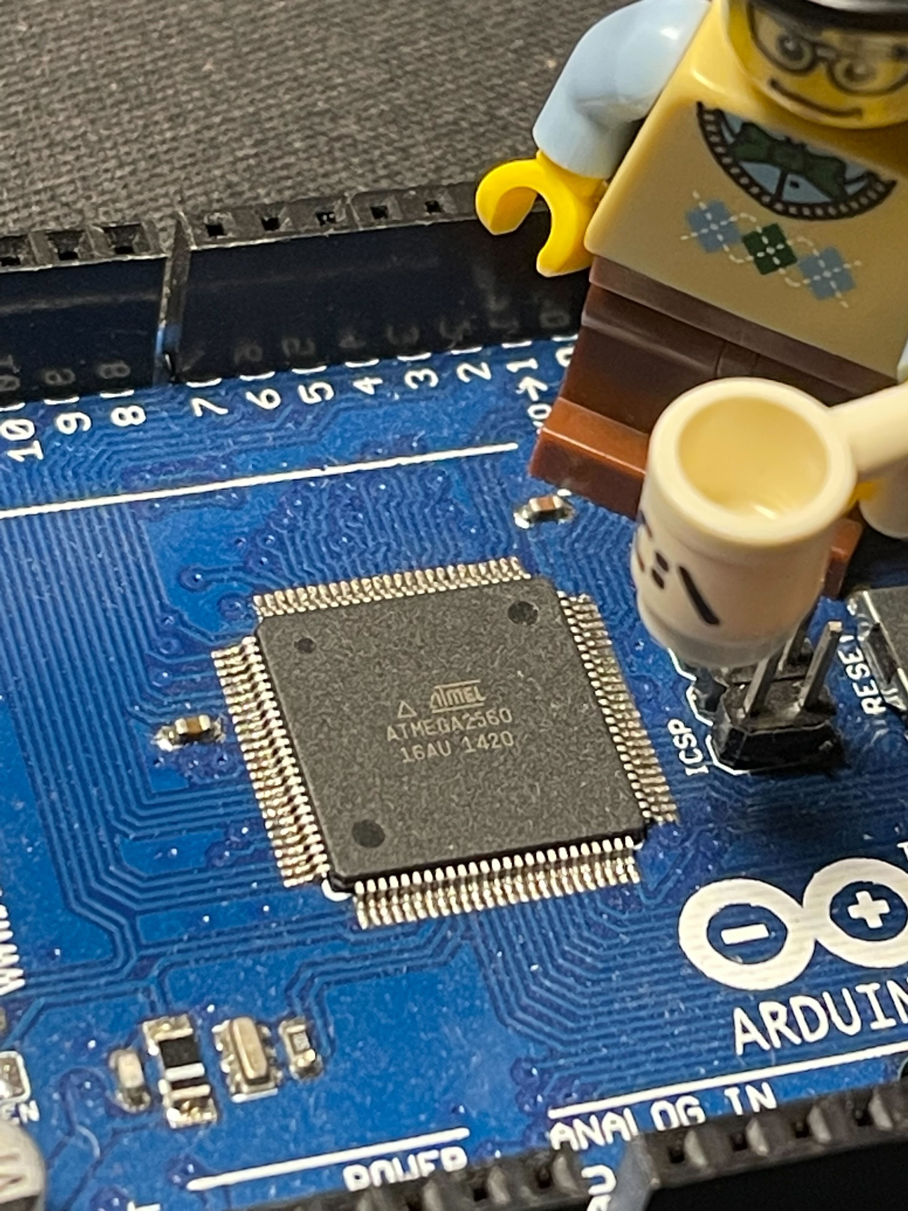
There are a LOT of new concepts in the datasheet, right now I cannot accomodate most of them in this learning path, but sure at some point later they will come back as I gain more knowledge.
I will start with the most obvious one, the CPU. The datasheet (section 7.1) explains that the CPU will:
- Access memories 🚪
- Perform calculations 🖩
- Control peripherals 💡
- Handle interrupts ✋
I will go through each of these concepts one by one, they seem fundamental!
Access memories 🚪
My laptop’s CPU makes the calculations and the RAM memory provides a storage for the input and ouput of those calculations. In my laptop, I have a CPU with 4 cores running at 1.8 GHz and 16 GB of memory. And now, the Arduino Mega that have 1 core and max 16 MHz and 8 kB of memory, the difference is huge but of course it is an unfair comparison like comparing 🍎 to 🍐.
The datasheet’s first page mentions 3 types of memories:
- 256 KB of flash
- 4 KB EEPROM
- 8 KB SRAM
I checked on wikipedia, the types of memories are:
Volatile : loses data when power-off 🪫
- RAM (random access memory) : read/write memory
- DRAM (dynamic RAM): the one my computer uses. The electric charge that stores data slowly leaks out and must be periodically be rewritten (refreshed). Cheapest and highest in density RAM, that is why we get GB of RAM in our computers.
- SRAM (static RAM): the one in my Arduino Mega. Does not require refresh. By the way, it is used in computers where the CPU has a small cache memory.
- RAM (random access memory) : read/write memory
Non-volatile: keeps data when power-off 💾
- ROM (read only memory) : well what use can it have if I cannot write to it? well you can write to it if you use an EEPROM (a type of ROM). The writing process is slow. It usually stores system software like BIOS.
- Flash memory : intermediate speed between EEPROM and RAM memory, used generally for storing our files, photos, etc. Or in the arduino to store the flashed code that will run.
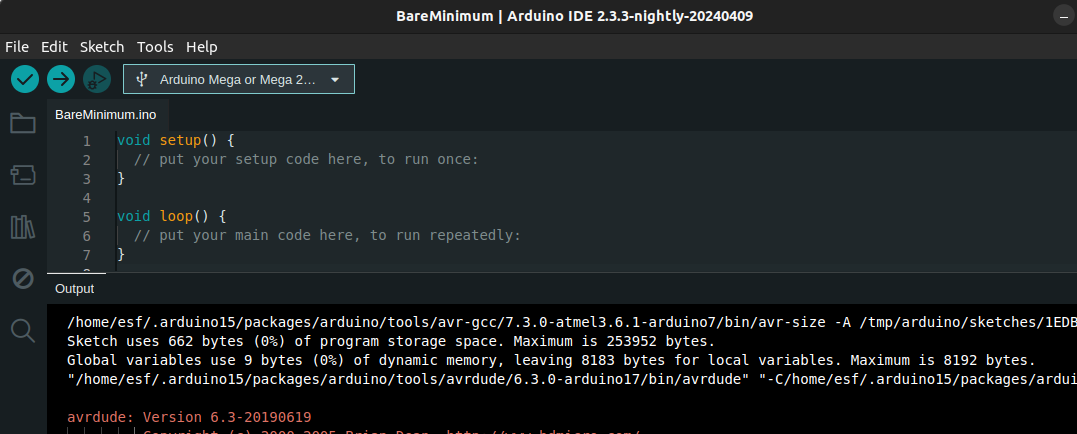
I actually realized that the Arduino IDE explains well its memory limits, if you use a bare minimum example with no variables only setup and loop defined, we can see the compiled storage space of 662 bytes (max 256 kB) and GLOBAL variables are 9 bytes (for SRAM with a limit of 8 kB) . It is interesting to see that even an empty sketch has some extra code behind that I will check later what exactly is.
Another aspect to take into account is the time difference between type memories, my computer’s cpu runs at 1.8 GHz so each clock cycle takes 1/(1.8E10+9) ~ 0.5E10-9 s (0.5 nanoseconds) , but how much time does it take to get info from memory?, I don’t know exactly how to test that in my computer or in my arduino. I found some rough values of what the memory hierarchy in my computer would look like see next pic:
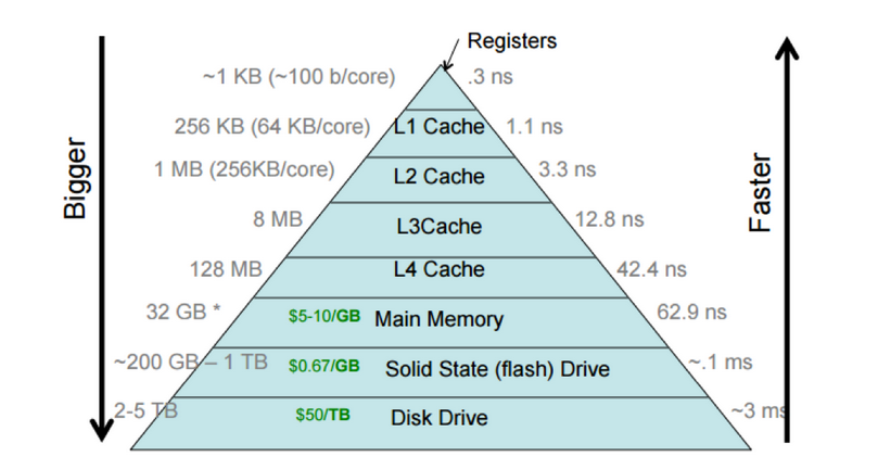
I can see cache memories (SRAM) are very fast 1-50ns , then the DRAM with 60 ns and after the storage SSD with 1 ms.
As summary, the memories in AVR chip are used for (source):
- Flash : where system’s firmware is stored. The firmware is the binary compiled and flashed to micro.
- EEPROM: it is a tiny hard drive if you need to save data. And the arduino docs says that EEPROM write takes 3.3 ms to complete. so you may need to be careful about how often you write to it.
- SRAM: storing variables created by the functions of a program.
But wait a sec, what is a register as shown in pic above?, the datasheet mentions there are 32x8 bit general purpose working registers with a single clock cycle access time. Therefore the fastest access time, as seen in above pic, register have 0.3 ns in line with my computer cpu of 0.5 ns period.
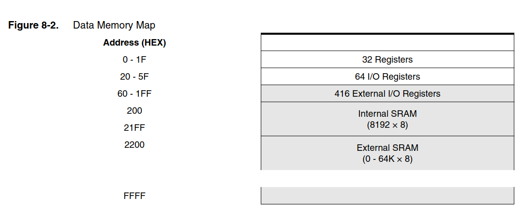
Another important aspect is to know how the memory is stacked , for that we have the memory map:
Perform calculations 🖩
The high-performance AVR ALU operates in direct connection with all the 32 general purpose working registers. Within a single clock cycle, arithmetic operations between general purpose registers or between a register and an immediate are executed. The ALU operations are divided into three main categories – arithmetic, logical, and bit- functions.
Control peripherals 💡
The I/O memory space contains 64 addresses for CPU peripheral functions. The I/O Memory can be accessed directly from address 0x20 to 0x5F. Why from 0x20? 0x20 in decimal is 32, meaning the first 32 addresses are for the general purpose register.
Handle interrupts ✋
The microcontroller’s code run in a loop, inside the loop you may do several operations, for example in a drone or RC plane we can have polling tasks like reading sensors, logging info to SD, receiving RC commands or output to actuators. What would happen if the micro is logging info to SD when an RC command is received?, would we missed it? it is possible 💨. For not missing an input reading, we can use interrupts. Interrupt will be triggered by the input and inmediately hold the loop so the input can be processed. This way we can efficiently use the micro because we are not polling all the time.
✅ Polling task : the micro will check if task can start or not , f.e. if a button is pressed then turn on a led, the micro will constantly poll if button is pressed.
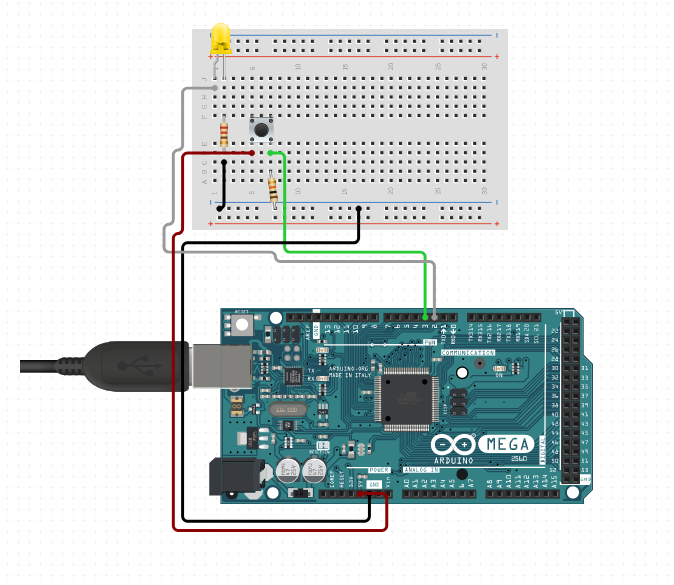
button_no_interrupt.ino
const int buttonPin = 3;  // the number of the pushbutton pin
const int ledPin = 2;    // the number of the LED pin


void setup() {
  // initialize the LED pin as an output:
  pinMode(ledPin, OUTPUT);
  // initialize the pushbutton pin as an input:
  pinMode(buttonPin, INPUT);
}

void loop() {
  // check if the pushbutton is pressed.
  if (digitalRead(buttonPin) == HIGH) {
    // turn LED on:
    digitalWrite(ledPin, HIGH);
  } else {
    // turn LED off:
    digitalWrite(ledPin, LOW);
  }
}
button_with_interrupt.ino
const int buttonPin = 3;  // the number of the pushbutton pin
const int ledPin = 2;    // the number of the LED pin

void setup() {
  // initialize the LED pin as an output:
  pinMode(ledPin, OUTPUT);
  // initialize the pushbutton pin as an input:
  pinMode(buttonPin, INPUT);
  // set interrupt
  attachInterrupt(digitalPinToInterrupt(buttonPin), blink, CHANGE);
}

void loop() {
}

void blink() {
  // check if the pushbutton is pressed.
  if (digitalRead(buttonPin)==HIGH){
    // turn LED on:
    digitalWrite(ledPin, HIGH);
  }else{
    // turn LED off:
    digitalWrite(ledPin, LOW);
  }
}
Both codes above do the same thing, led is ON when button is pressed. The difference is
that without interrupt , we are constantly reading buttonPin state digitalRead(buttonPin) to
check if HIGH or LOW. On the other hand with interrupt, we only do that check once per button state change with .
Notice that in essence, we are moving the function out of the loop to only
be run when an “event” happens. This event can be hardware(external interrupt) or triggered from
software (f.e. if I have enough data or elapsed time has passed then I log info to SD card).
🚀 Interrupt response time is at least 8 clock cycles, then the minimum reaction time will be
at least 500 ns or 0.5 μs (each clock cycle in Arduino is 62.5 ns with 16 MHz clock speed). When using
the attachInterrupt fuction as used above, there are in total 82 cycles -> 5.125 μs before entering your
interrupt function.
The main reasons you might use interrupts are:
- To detect pin changes (eg. rotary encoders, button presses)
- Watchdog timer (eg. if nothing happens after 8 seconds, interrupt me)
- Timer interrupts - used for comparing/overflowing timers
- SPI data transfers
- I2C data transfers
- USART data transfers
- ADC conversions (analog to digital)
- EEPROM ready for use
- Flash memory ready
Wake the processor (source)
External interrupts, pin-change interrupts, and the watchdog timer interrupt, can also be used to wake the processor up. This can be very handy, as in sleep mode the processor can be configured to use a lot less power (eg. around 10 microamps). A rising, falling, or low-level interrupt can be used to wake up a gadget (eg. if you press a button on it), or a “watchdog timer” interrupt might wake it up periodically (eg. to check the time or temperature). Pin-change interrupts could be used to wake the processor if a key is pressed on a keypad, or similar. The processor can also be awoken by a timer interrupt (eg. a timer reaching a certain value, or overflowing) and certain other events, such as an incoming I2C message.